How Check Valves Prevent Backflow in Fluid Systems
Backflow is one of those fluid-system problems that looks simple on paper and expensive in practice. When media reverses direction, it can contaminate a clean supply, drain pressure from a working circuit, damage pumps, upset calibration, and create safety risks in water, lubrication, fuel, and pneumatic systems.
That is why check valves remain a core part of smart system design. They allow flow in one direction and close when pressure reverses. In many assemblies, that one action protects equipment, product quality, and uptime. In others, especially potable water systems, the check valve is only one layer in a larger backflow prevention strategy.
What backflow means in fluid systems
Backflow is the unwanted reversal of fluid through a line or connected system. In industrial settings, that can mean contaminated water moving into a clean line, pressurized media returning toward a pump, or lubricant escaping from a fitting when system pressure shifts.
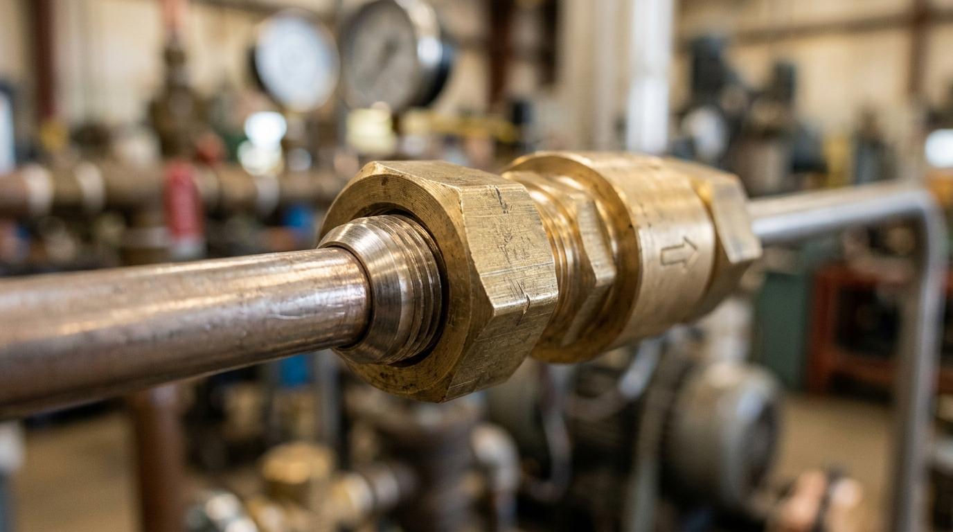
The term matters because reverse flow is not limited to one application. It shows up in process piping, compressed air systems, water service lines, lubrication circuits, and mobile equipment. Even compact assemblies that use inverted flare brass fittings or other tube fittings can be affected if pressure relationships change across the line.
A useful way to frame the risk is this: fluid will always move from higher pressure to lower pressure, and a system does not care which direction the designer intended.
How a check valve stops reverse flow
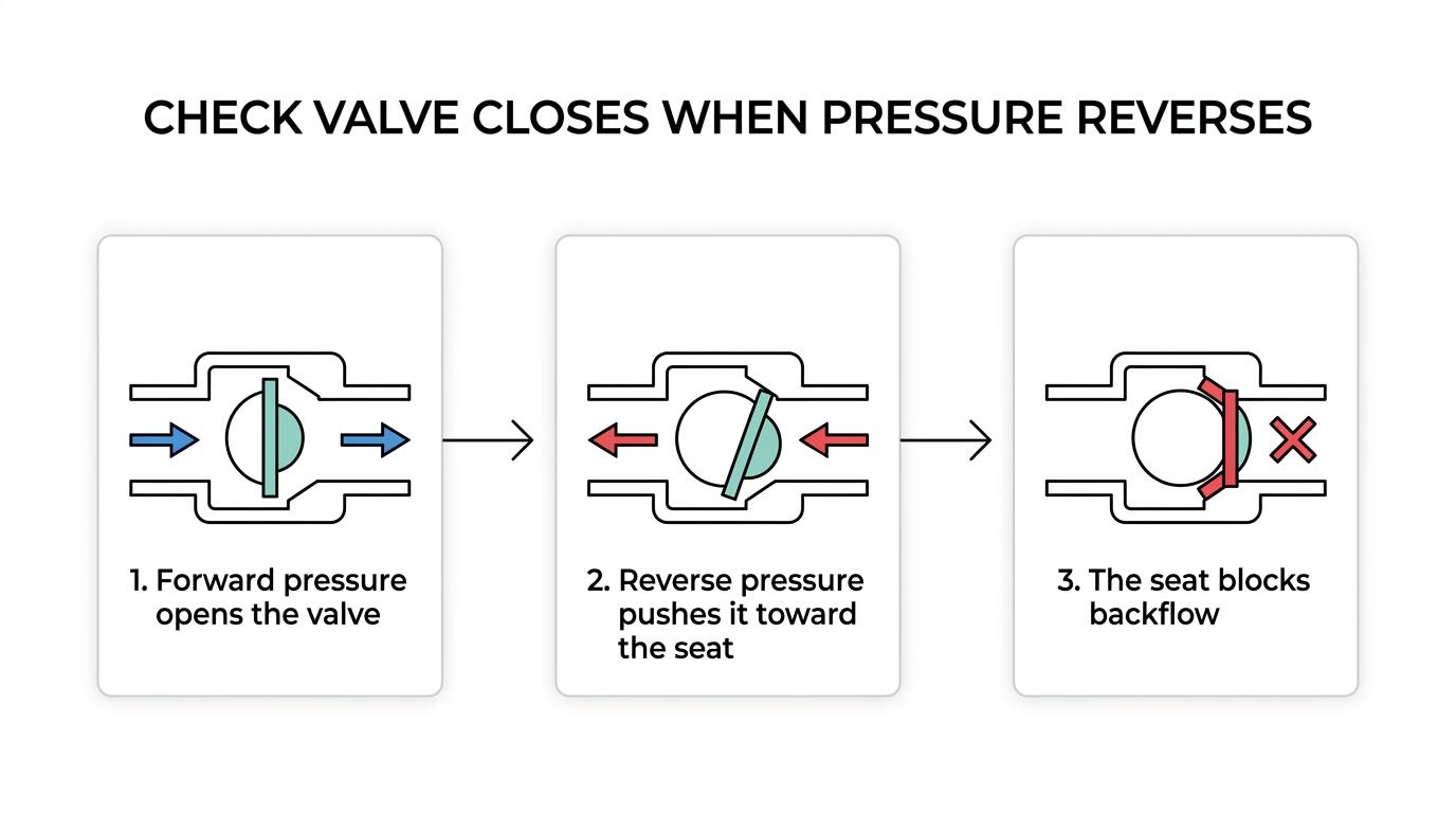
A check valve is built to open when upstream pressure exceeds downstream pressure by enough to overcome the internal closing force. That closing force may come from gravity, a spring, or the geometry of the moving element. When flow tries to reverse, the internal element moves to the seat and blocks the passage.
In practical terms, the valve reacts to differential pressure. During normal forward flow, the disc, poppet, or ball lifts off the seat. When the pressure gradient drops or reverses, the valve closes. This is why check valves are widely used to prevent backflow through nonoperating components, idle branches, and equipment that must stay isolated from reverse movement.
Some designs close faster than others. Spring-loaded check valves are often chosen where quick closure is needed, especially when system pulsation or sudden pressure changes could create damaging reverse flow.
After the basic mechanism is clear, selection gets easier:
- Cracking pressure
- Flow direction
- Media compatibility
- Temperature range
- Pressure rating
- Orientation limits
Backpressure backflow and backsiphonage are not the same problem
Not all backflow events happen the same way. Two common causes are backpressure backflow and backsiphonage, and the difference matters when specifying protection.
Backpressure backflow happens when pressure on the downstream side becomes greater than the supply pressure upstream. That can occur when a booster pump starts, a vessel is pressurized, elevation creates added head, or thermal expansion changes the pressure balance. The result is fluid trying to move the wrong way.
Backsiphonage is different. It occurs when the upstream supply pressure drops low enough that fluid is drawn backward through a cross-connection. A water main break, heavy system demand, or a rapid drain-down can create that condition.
A single check valve helps with one-way flow control, but regulated public water systems often need assemblies designed for the specific hazard and the specific backflow mode. That is where the conversation moves beyond a standalone valve.
Where check valves fit in regulated backflow prevention
In industrial equipment, a single check valve may be enough to stop reverse flow inside a contained process circuit. In potable water protection, code and hazard level drive a more structured approach.
Public water backflow controls often use assemblies built around one or two check valves plus other components. A double check valve assembly uses two independently acting check valves and is commonly applied where nonhealth hazards are involved. A reduced pressure principle assembly adds a pressure differential relief valve to provide stronger protection in higher-risk conditions. A pressure vacuum breaker assembly combines a check valve with an air inlet valve to address backsiphonage concerns.
That distinction matters for engineers and buyers because a check valve is not automatically a complete backflow prevention solution. It is a core device, but the full assembly may need relief, venting, test cocks, shutoff valves, or annual certified testing depending on the application and local requirements.
The table below offers a quick comparison.
| Device type | Primary function | Typical use case | Notes |
|---|---|---|---|
| Single check valve | Stops reverse flow in one direction | Equipment protection, pump discharge, branch isolation | Good for internal system control, not always enough for regulated potable water protection |
| Double check valve assembly | Uses two check valves in series | Nonhealth hazard backflow control | Addresses backpressure and backsiphonage in many nonhealth hazard cases |
| Reduced pressure principle assembly | Two check valves plus relief valve | Higher hazard water protection | Used where stronger isolation is required |
| Pressure vacuum breaker assembly | Check valve plus air inlet valve | Backsiphonage protection | Often selected where backpressure is not the main risk |
Why system connections matter as much as the valve
A check valve can only perform as well as the connections around it. Poorly matched threads, weak tubing support, or the wrong sealing method can create leakage, vibration issues, and false troubleshooting trails that look like valve failure.
This is where inverted flare brass fittings become part of the conversation. In brake line fittings, fuel line fittings, and certain pressure-sensitive tube assemblies, inverted flare fittings help create a durable metal-to-metal seal that resists vibration and repeated service. They do not replace a check valve, but they support overall flow-control reliability by keeping the line secure and leak resistant.
When engineers or procurement teams are reviewing tube connections around a valve station, it is helpful to compare inverted flare brass fittings with other brass adapters and tube fittings used in the same system. That is especially true when the line includes pulsing pressure, compact routing, or frequent maintenance access.
Good connection design often includes the following:
- Tube geometry: Correct tube OD, wall thickness, and flare form
- Material match: Brass flare fittings selected with compatible tubing and media
- Service conditions: Pressure, vibration, temperature, and duty cycle
- Maintenance access: Enough room for proper tightening and inspection
Common check valve designs and where they work best
No single check valve style fits every system. The right choice depends on pressure, orientation, flow pattern, contamination level, and desired closing response.
Swing check valves are simple and common in larger flow paths where low restriction is useful. Lift check valves are often used where a more guided closing element is preferred. Ball check valves can work well with certain fluids and compact layouts. Spring-loaded check valves are often chosen where quick closing action helps reduce reverse-flow effects.
Vertical and horizontal installation also matter. Some valves depend on gravity and must be mounted in a certain position. Others are spring assisted and more tolerant of orientation changes. That point is easy to miss during sourcing, especially when a team is focused on port size and pressure rating alone.
In smaller tube systems, the valve body and the connecting hardware should be reviewed together. A compact one-way valve paired with SAE inverted flare fittings or brass adapters can make installation cleaner and service more repeatable than a mixed-connection assembly built from whatever is on hand.
How check-valve behavior shows up in lubrication systems
One of the clearest examples of simple backflow prevention is found in lubrication hardware. Grease fittings often use check-valve designs that allow grease to enter under pressure while helping prevent leakage when pressure would otherwise push material back out.
That small internal check action matters. It keeps contaminants out, reduces mess, and helps maintain lubrication where it belongs. In a maintenance environment, that can improve cleanliness and reduce wasted lubricant over time.
The lesson carries into broader fluid systems: backflow control is not always about large pipelines. Sometimes it is about protecting a small point of entry from reverse pressure and leakage.
Signs a check valve may not be preventing backflow properly
A failing or poorly selected check valve does not always announce itself with a dramatic event. Many problems start with subtle system symptoms.
You may see pressure decay, pump short cycling, contaminated return flow, reverse wheel-circuit drainback, or a line that needs repeated priming. In regulated water protection, performance issues may only be confirmed through formal testing of the assembly.
After those symptoms appear, typical causes include:
- Worn seat: Reverse leakage past the sealing surface
- Debris intrusion: Particles keep the closure element from sealing fully
- Wrong orientation: Valve cannot close as intended in service
- Low differential pressure: Insufficient force to move or hold the element correctly
- Fatigue
- Corrosion
- Improper sizing
Selection factors for buyers, engineers, and technicians
Choosing a valve for backflow prevention is rarely just a valve decision. It is a system decision. Media type, code requirements, line pressure, pulsation, maintenance interval, and end connection style all shape the right answer.
For industrial buyers, the specification should separate two questions. First, do you need one-way flow control inside a machine or process loop? Second, do you need a tested backflow prevention assembly for a regulated supply connection? Those are related, but not identical, needs.
Connection strategy should also be addressed early. If the assembly includes tube runs rather than threaded pipe alone, inverted flare brass fittings may be the better choice where vibration resistance, serviceability, and compact sealing surfaces are needed. In brake line fittings, fuel line fittings, and similar tube circuits, flare and inverted flare fittings can support a more stable installation around valves and pressure-control components. A good reference point for those applications is this category of flare and inverted flare fittings.
A solid review process usually covers:
- Flow direction and normal operating pressure
- Reverse-pressure risk from pumps, tanks, elevation, or shutdown conditions
- Media compatibility with brass, seals, and tubing
- Port style, including pipe threads, tube ends, and brass flare fittings
- Inspection, testing, and replacement access
Testing, maintenance, and lifecycle performance
Even a well-chosen check valve is still a moving component. Wear, fouling, and pressure cycling will affect performance over time.
In industrial service, periodic inspection should match the severity of the duty cycle. Systems with dirty media, frequent cycling, or high consequences of reverse flow should be checked more often. A quiet, stable process line may need less attention than a pulsating pump discharge or an outdoor water assembly exposed to debris and temperature swings.
For regulated backflow prevention assemblies, routine testing is not optional in many jurisdictions. Required assemblies are commonly tested at least annually by certified personnel. That reinforces an important point: backflow prevention is part device, part installation practice, and part verification program.
Documentation helps here. When procurement, engineering, and maintenance teams record valve type, cracking pressure, orientation, connection style, and replacement intervals, troubleshooting gets faster and repeat purchases get more accurate.
A practical way to build more reliable one-way flow control
Start with the pressure story of the system. Identify where reverse flow can occur during normal operation, shutdown, upset conditions, and maintenance. Then match the valve style to that reality rather than defaulting to a familiar part number.
After that, review the connections with equal care. Reliable tube assemblies often depend on details that look minor during design review but matter every day in service. That is one reason inverted flare brass fittings remain relevant across fuel, brake, and general tube-fitting applications. When paired correctly with check valves, brass adapters, and properly prepared tubing, they help create a tighter, more dependable flow path.
Backflow prevention works best when the valve, the fitting, and the operating conditions are treated as one system instead of separate parts.
Keywords:
how check valves prevent backflow